
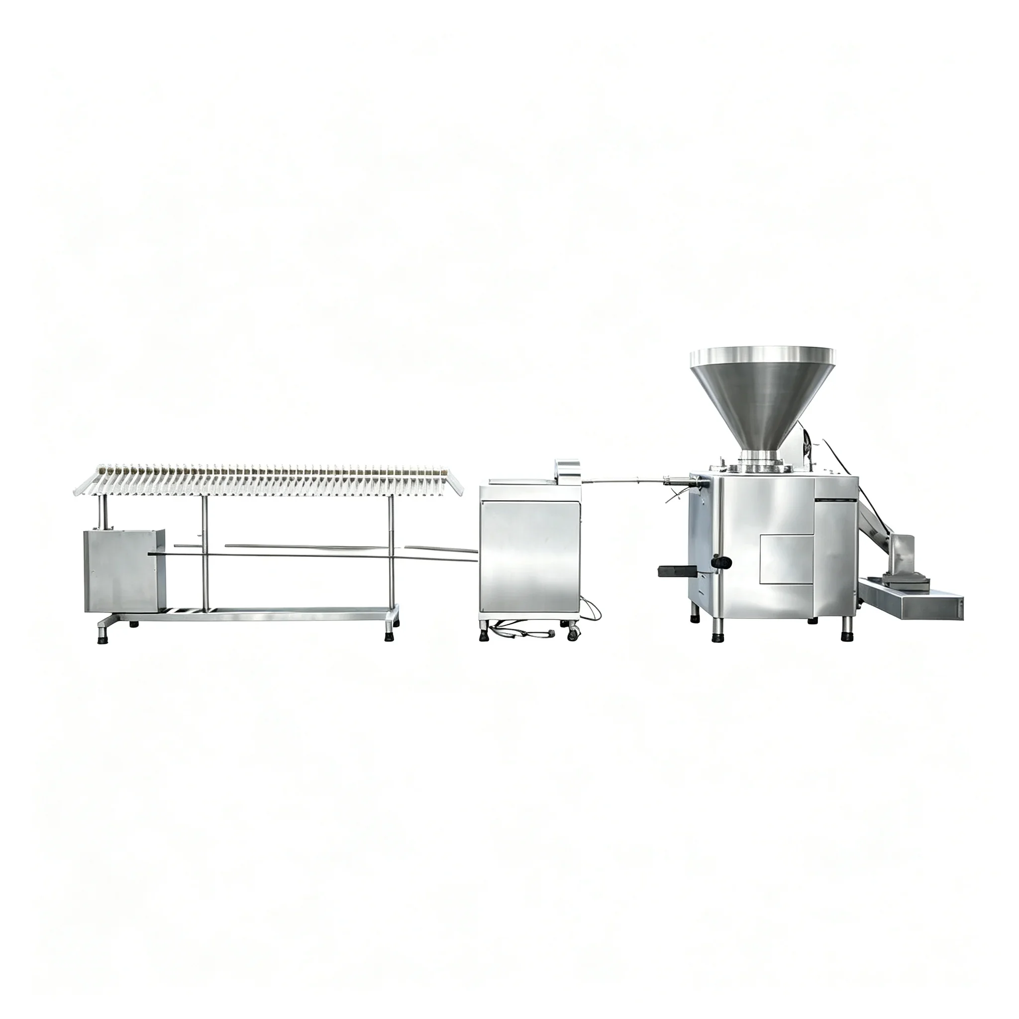
Hot dog production runs at unforgiving speed — a vacuum filling machine operating at 4,000–6,500 kg/h outpaces any manual handling step within seconds. The only way to sustain that throughput is a fully integrated, electronically synchronised line where the filler, clipping unit, and hanging conveyor share a single speed reference. This guide covers the integration architecture, control requirements, and critical mechanical interfaces for connecting a vacuum filling machine to an automatic clipping line for hot dog and frankfurter production.
Understanding the Integration Challenge
A vacuum filler and an automatic clipping or tying machine are two mechanically independent systems with different inertia characteristics, different control loops, and different failure modes. At low speed, the gap between them is manageable — operators can physically manage casing slack. At high speed, any speed mismatch creates back-pressure at the filler nozzle within 2–3 seconds, causing weight deviation, air pockets, or casing rupture. Integration is not simply about connecting the machines physically; it is about making them behave as a single servo system.
The Three Integration Layers
Mechanical Interface
The stuffing horn exit and clipping unit inlet must share a common casing path geometry. Horn diameter, exit angle, and casing tension at the transition point determine whether the casing runs smooth or bunches. This is set at installation and rarely adjusted — get it right the first time with the supplier’s integration drawing.
Electronic Speed Sync
Filler and clipper share a speed reference signal — typically a 0–10V analogue or CANopen digital link. When the filler speed controller changes its output, the clipper’s drive receives the same correction within one control cycle (typically 10–20ms). This prevents the speed mismatch accumulation that causes back-pressure.
PLC Interlock Logic
Fault signals must cross-link: a jam at the clipper must trigger an immediate filler stop. A filler hopper low-level signal must trigger a controlled clipper deceleration. These interlocks prevent the common failure mode of one machine running into a stopped downstream unit.
Selecting the Right Automatic Clipping Unit for Hot Dog Lines
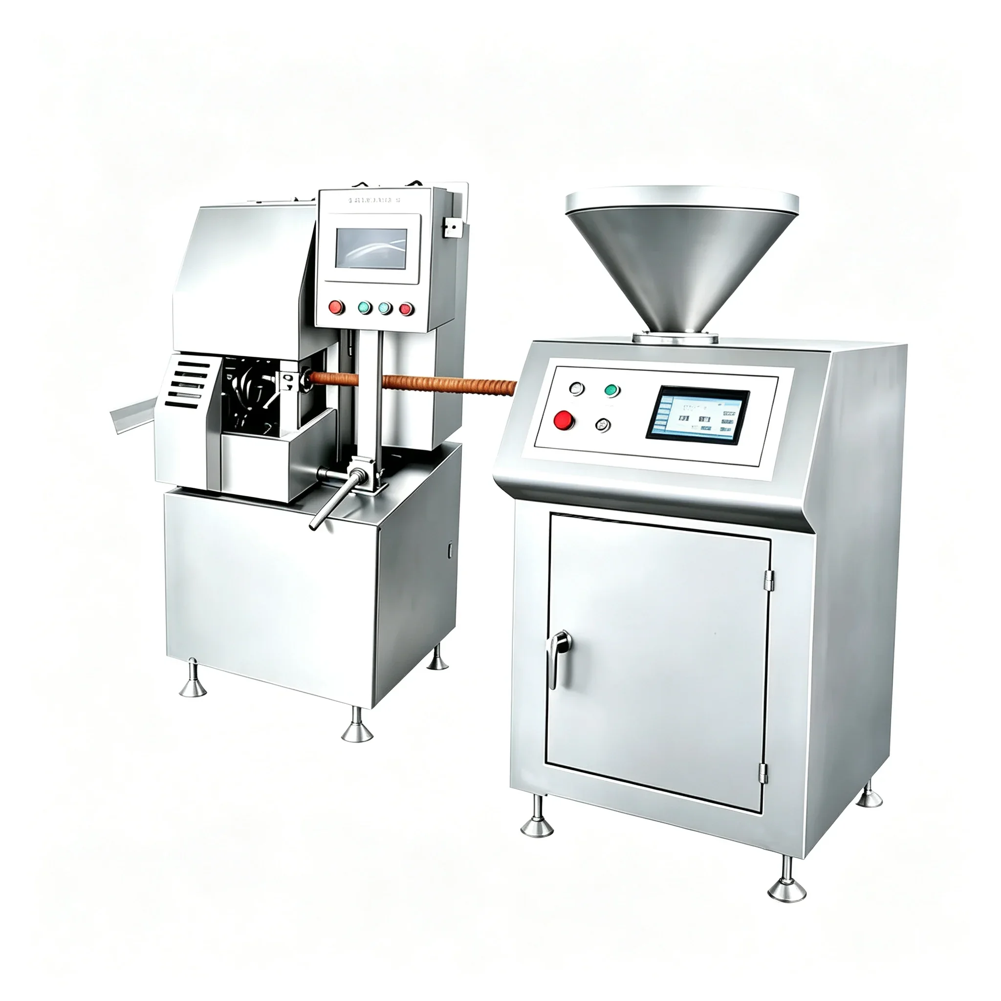
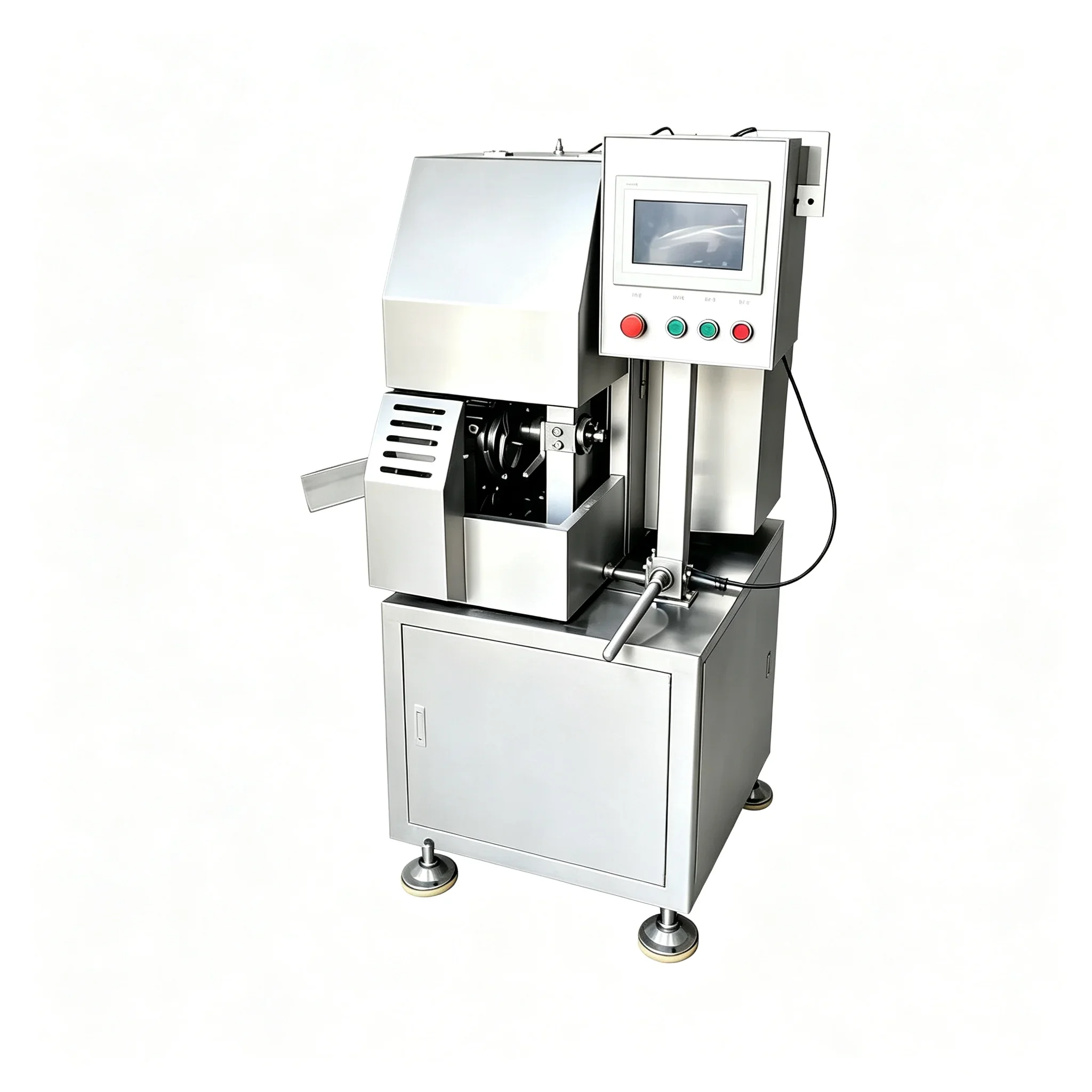
Not all automatic clipping machines are designed for the throughput and clip pitch required by hot dog production. A standard frankfurter at 50–80g requires clip pitch control to ±1mm to maintain consistent link length and portion weight. The JLSK-II aluminum wire double clipping machine is designed for continuous high-speed operation with adjustable pitch and dual-clip capability, which is standard for hot dog formats that require a clip at both ends of each link.
For large-diameter hot dogs (28mm+), the clipping unit must also handle the greater casing tension generated at larger calibers. Clip tension that is adequate for a 20mm link will under-seal a 28mm one — the clip wire cross-section and jaw closure force must be specified to the casing diameter, not just the product type.
Control Architecture: Shared PLC vs Master–Slave Drive
Shared PLC Architecture
Both the filler and clipping unit connect to a single PLC that manages speed reference, interlock logic, and fault handling. This approach gives maximum flexibility for adding future stations (hanging conveyors, smokehouses) to the same control loop. It requires a PLC with sufficient I/O capacity and a programmer familiar with drive synchronisation — typically the equipment supplier’s responsibility at commissioning.
Master–Slave Drive Architecture
The filler drive acts as master; the clipping unit drive follows its speed reference directly via an encoder follower or digital speed link. This is simpler to commission and more robust against PLC failures — if the PLC faults, the drives continue to run synchronised. The limitation is that interlock logic must be handled separately (hardwired relays or a safety PLC), which adds wiring complexity.
| Architecture | Sync Accuracy | Complexity | Fault Tolerance | Best For |
|---|---|---|---|---|
| Shared PLC | ±5ms | High | PLC is single point of failure | New lines, multi-station integration |
| Master–Slave Drive | ±2ms | Medium | Drives stay synced if PLC faults | Two-unit lines, retrofit integration |
| Hardwired Analogue | ±15–30ms | Low | High — no digital dependency | Older equipment, budget retrofit |
| EtherCAT / Profinet | ±0.5ms | High | Requires managed switch redundancy | Precision lines, checkweigher integration |
Casing Tension Management Between Filler and Clipper
The section of filled casing between the filler nozzle exit and the clipper jaw is the most mechanically vulnerable point in the line. It must maintain consistent tension — enough to keep the casing taut for accurate clip positioning, but not so much that it stretches the casing and distorts the link. For collagen casing hot dogs, target tension is typically 0.8–1.2N at the casing wall.
A dancer roller or passive tension buffer between the two units provides mechanical compliance for the 80–150ms speed correction lag that exists even in well-integrated electronic systems. This roller absorbs the micro-slack variations that occur during acceleration and deceleration events, preventing those variations from reaching the clip jaw as positional errors.
Hanging Line Integration After Clipping
After clipping, hot dogs must transfer to a hanging conveyor or smoker trolley at line speed. The YZG-1200 automatic sausage linking hanging line accepts clipped links directly from the clipper exit and arranges them on hanging rods without manual handling. This is the stage where most manual labour is traditionally concentrated — and where integration delivers the greatest labour cost reduction per unit of output.
The hanging unit must be speed-matched to the clipper (which is itself speed-matched to the filler), extending the synchronisation loop to three stations. Each additional station multiplies the importance of clean interlock logic — a fault at station 3 must stop stations 1 and 2 in the correct sequence to prevent casing pile-up.
Commissioning Checklist for a Fully Integrated Hot Dog Line
Mechanical alignment
Stuffing horn axis, clipper inlet, and hanging conveyor entry aligned to within 2mm on a single centreline.
Speed sync test
Run at 25%, 50%, 75%, and 100% speed; log weight at each level. Deviation should not increase proportionally with speed if sync is clean.
Fault interlock test
Simulate each fault condition (filler hopper empty, clipper jam, hanging unit stop) and verify correct stop sequence.
Back-pressure check
At full speed, verify nozzle pressure does not spike above ±0.02 bar from baseline during steady-state operation.
Casing tension measurement
Measure tension at the dancer roller under load; adjust roller spring if outside 0.8–1.2N target range.
Weight audit
Run 200 consecutive links, weigh every 10th. Deviation should fall within ±1.5g for collagen casing at full speed.
Ready to Optimise Your Sausage Production Line?
Send us your output targets and casing spec — we respond within 48 hours.
+86 13083988828 | ✉ [email protected]